This article was co-authored by Dan Kelcher, Solutions Architect at IP Fabric
In part 3 of this series on PCI compliance, we covered how you can satisfy parts of requirements 1 and 12 of the PCI DSS by leveraging IP Fabric to obtain a complete network inventory and to visualize your network with up-to-date topological overviews and network diagrams. So now that you have this inventory (including end-of-life data and vendor-suggested replacements), and a network diagram that can be updated ad-hoc without reliance on manual documentation, you can begin to investigate the dataflow within your network and further protect yourself from any potential issues during your next PCI compliance audit.
Let's dig in and see how IP Fabric's path tracing capabilities can allow you to satisfy some additional requirements set out by the PCI DSS. In this series entry, we will partially cover further sub-requirements within requirement 1, as well as part of requirement 11, as set out by the PCI DSS.
Here are the specific requirements within 1 and 11 that can be satisfied using the path tracing function:
As mentioned in part 3 of this series, requirement 1.2.4 touches upon path tracing. The requirement itself states that enterprises possess an accurate dataflow diagram, maintained to meet the following: a) It shows all account data flows across systems and networks, and b) it is updated as needed upon changes to the environment.
1.3.1 specifies that inbound traffic to the card data environment (CDE) be restricted to only necessary traffic, with all other traffic being specifically denied. All unauthorized traffic cannot be able to enter the CDE. This is intended to prevent "malicious individuals" from accessing the network via unauthorized IP addresses.
1.3.2 stipulates that outbound traffic from the CDE be restricted to only necessary traffic, with all other traffic being specifically denied.
1.4.1 mandates that Network Security Controls (NSCs) be implemented between trusted and untrusted networks, so that unauthorized traffic cannot traverse network boundaries between those trusted and untrusted networks. This requires an examination of configuration standards and network diagrams to verify that NSCs are defined (1.4.1.a), and that these are in accordance with documented configuration standards and network diagrams (1.4.1.b).
1.4.2 requires inbound traffic from untrusted networks to trusted networks be restricted to: a) communications with system components that are authorized to provide publicly accessible services, protocols and ports, and b) stateful responses to communications initiated by system components in a trusted network, with all other traffic being denied. Essentially, only authorized traffic or responses to a system component (in the trusted network) can enter from an untrusted network.
1.4.4 requires system components that store cardholder data (CHD) to not be directly accessible from untrusted networks. This requires an examination of the dataflow and network diagram to verify that system components storing CHD are not directly accessible from said untrusted networks (1.4.4.a). Also required is an examination of NSC configurations to verify that controls are properly implemented to ensure that CHD-storing components are not directly accessible from untrusted networks (1.4.4.b).
11.4.5 states that if segmentation is used to isolate the CDE from other networks (see part 2 for more detail on network segmentation and PCI compliance), penetration tests are performed on segmentation controls. This must be performed AT LEAST once every 12 months and after changes to segmentation controls and methods. The CDE must be confirmed as sufficiently isolated from all out-of-scope systems.
1.2.4 – By providing a source and destination within your network, IP Fabric can show the path that data takes through the network. These can be generated on-demand or configured to run automatically. The ability to generate these on-demand helps to satisfy requirement 1.2.4, as administrators can run these regularly to ensure they are kept current and accurate. This also provides an easy view of all devices that would be in-scope for a PCI compliance audit, meaning any devices within that data flow would need to be PCI compliant.
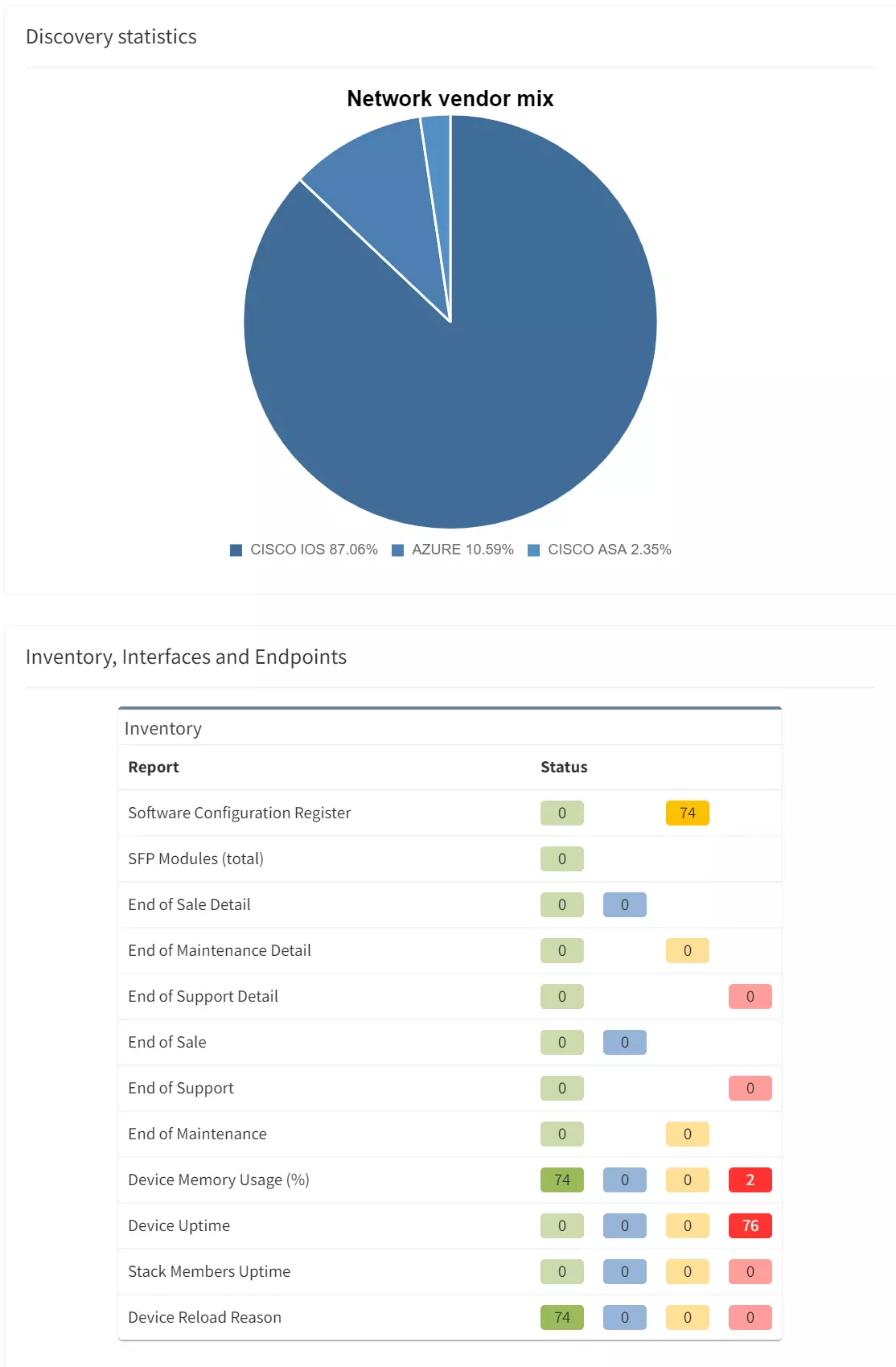
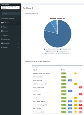
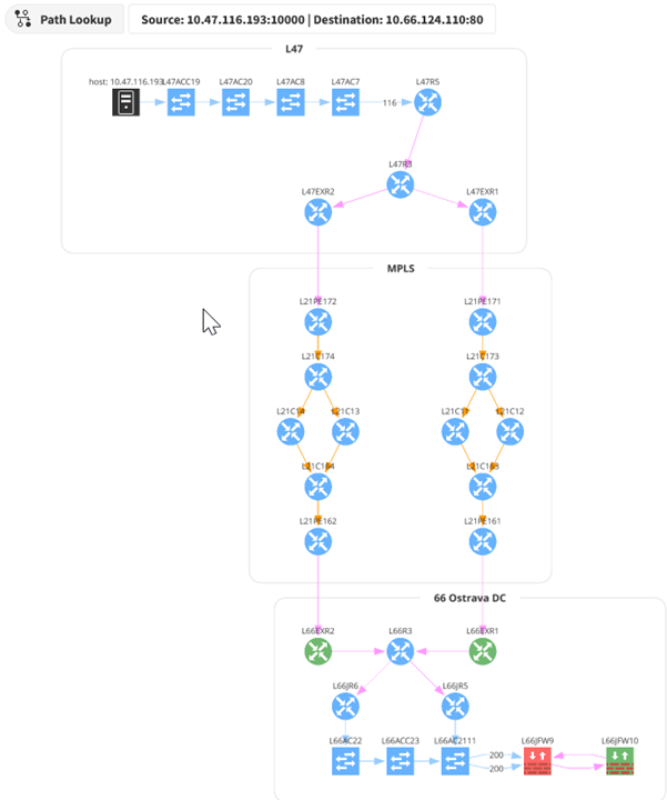
How does it work? When a snapshot of the network is taken, IP Fabric captures the state of each device, including CDP/LLDP, MAC table, and routing table information. That data is used to determine the relationship between devices. A graphical topology can be built from that relationship information.
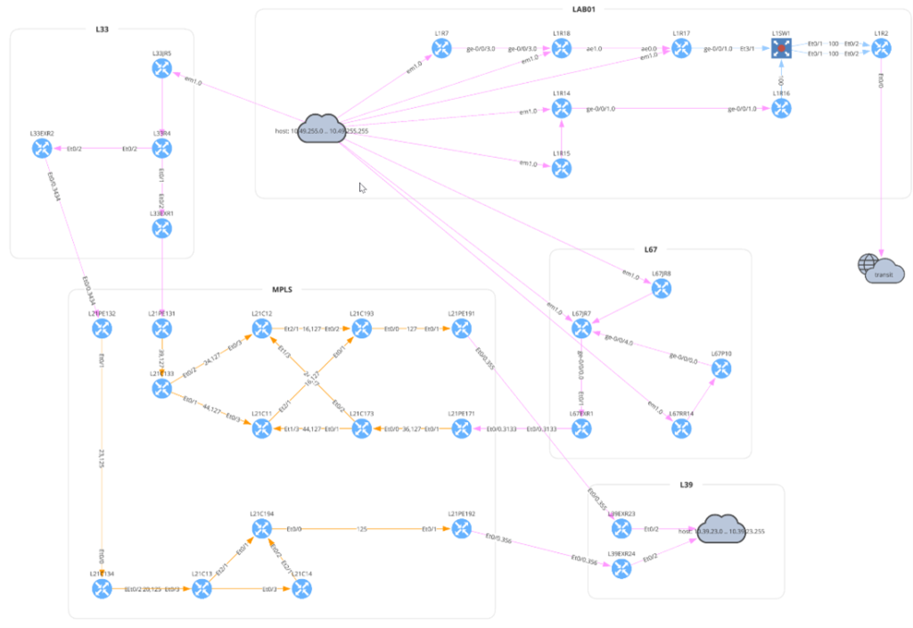
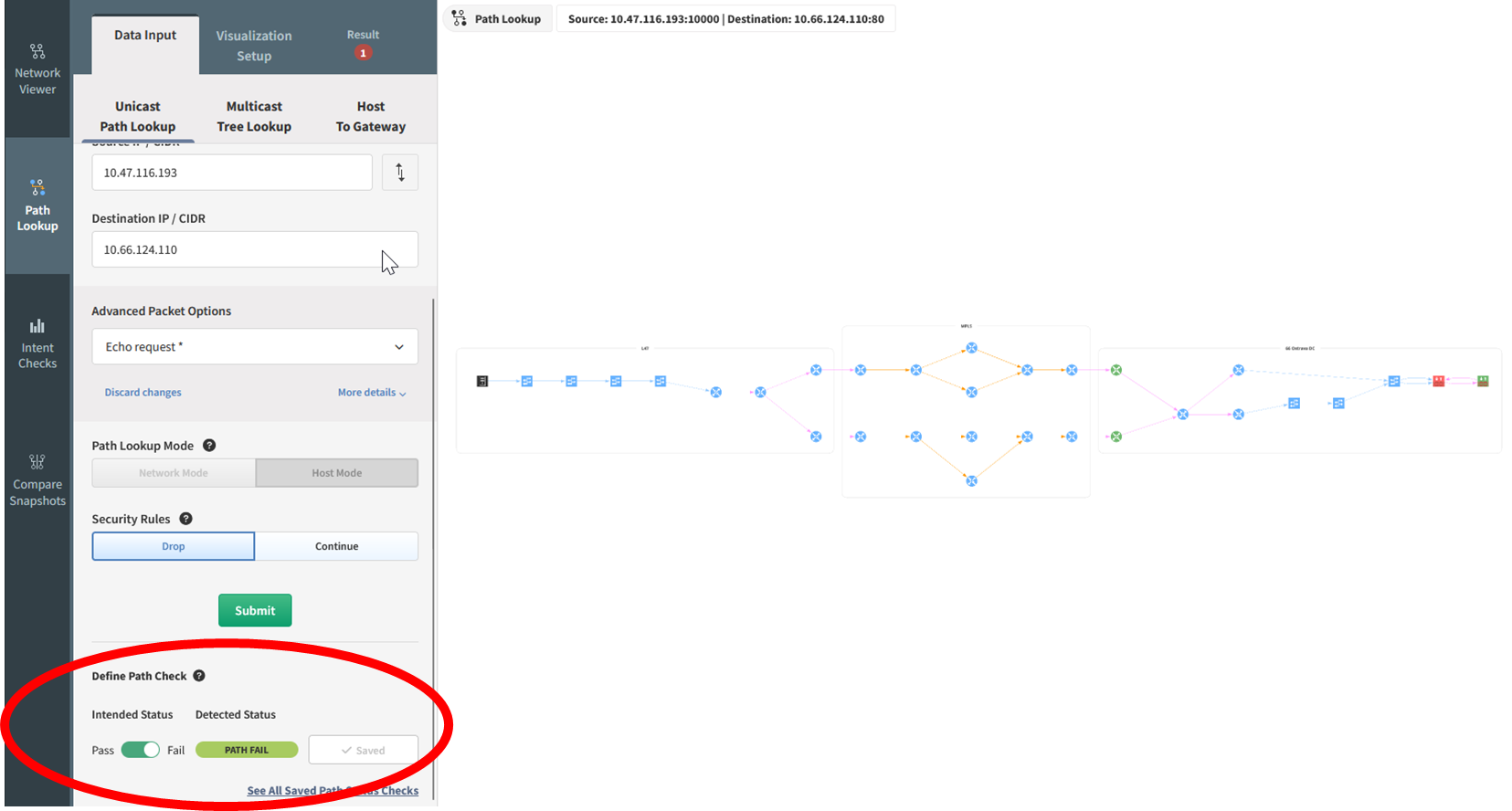
In the above diagram, the traffic flow starts at the top left, from host 10.33.230.2 in site L33. The router L33R4 has equal-cost load balancing, splitting traffic across two paths. The traffic flows through an MPLS network to the L81 site. The presence of the transit cloud in the lower left indicates the flow traverses through a device (or multiple devices) that IP Fabric does not know (often this would be a service provider’s network). The traffic finally reaches the destination on L81R5.
1.3.1 and 1.3.2 - Using the same path tracing tool allows you to determine whether traffic can enter or exit the CDE. A trace can be performed using specific source and destination IP addresses or using CIDR blocks and can include a defined protocol and port. This also allows for validation of the NSCs in place to ensure that only necessary traffic is flowing through these points. When a path trace is created, an intent rule is generated based on the intended status of that flow, be it pass or fail. Any deviation from what is expected or planned can be remedied by reinforcing the relevant NSCs to prevent any unnecessary traffic from entering, or exiting, where it should not be.
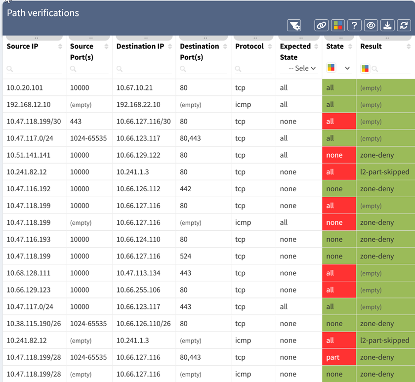
The above table shows the status of the path verification rules. The 5-tuple for each test is listed, along with the expected state (all allowed, or none allowed), the state of the test (all, part, or none of the traffic allowed), and the result which shows why traffic was blocked. The state is also color-coded, with green meaning the state matched expectations, and red signifying a deviation.
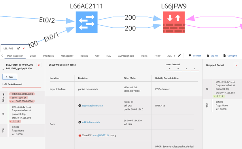
1.4.1 – Of particular interest within this requirement are 1.4.1.a and 1.4.1.b - These sub-requirements stipulate that configuration standards and network diagrams are verified (1.4.1.a), and in accordance with the documented standards for configuration standards and diagrams (1.4.1.b). With path tracing, you can determine where these NSCs are located, how they are configured, and whether this is sufficient to segregate trusted and untrusted networks. IP Fabric can also provide you with security assurance - You can standardize the management of your configurations and ensure that these align with your documented configuration standards required under 1.4.1.b. Standardizing the configuration management of NSCs reduces manual effort - Saving you additional time, effort, and brainpower in ensuring your NSCs are configured in accordance with your documented configuration standards before your next PCI compliance audit.
1.4.2 – Similarly to the requirements in 1.4.1, path tracing of the network and dataflow diagrams can be used to determine the flow of traffic between trusted and untrusted networks. As this requirement also stipulates that NSC configurations (and vendor documentation) be verified to determine if inbound traffic from untrusted to trusted networks is sufficiently restricted, IP Fabric’s security assurance can once again be used to standardize configuration management and ensure that these are sufficiently hardened against unwanted accesses.
1.4.4 – This requirement is also quite similar with regards to how IP Fabric can help. Using the network diagram that you have already built, you can verify if system components that store CHD are directly accessible from untrusted networks. Under 1.4.4.a, this means you have to verify your network and dataflow diagrams to ensure there is documentation that system components storing CHD is not directly accessible. Under 1.4.4.b, NSC configurations must be verified to ensure controls are in place to ensure CHD components are not accessible from untrusted networks. Again, with path tracing, and the ability to standardize configurations, you can ensure that these components are sufficiently protected and hardened against access from untrusted networks.
11.4.5 - As discussed in part 2, using your dataflow and network diagrams established by IP Fabric, you can verify whether you have sufficient segmentation in place. By locating the appropriate environments, you can verify whether segmentation is effective, prior to the investigation by an independent auditor.
Here's how simple IP Fabric makes this process:
This process can also leverage the API and webhook capabilities of IP Fabric. New path checks can be added programmatically and included in automation workflows. Webhooks can be configured to push information on failed intent checks into other platforms.
IP Fabric uses network configuration and state data to build out a representation of the network topology and can then determine how traffic would flow through the network, giving you all of the information that you need before your next PCI compliance audit. Adding intent rules to these path checks quickly and easily allows teams to identify problem areas. This visibility extends from a global topology view, down through a device level and into the detailed decisions made by network devices. That level of visibility simplifies both the environments' compliance state, as well as the process of gathering evidence to support either confirmation of compliance or the need for changes to achieve PCI compliance.
Follow us on LinkedIn and our blog, where we publish new content on a regular basis. For more information on how IP Fabric can help you to get to know your entire network inside and out, please request a demo here.
This article was co-authored by Dan Kelcher, Solutions Architect at IP Fabric
This article was co-authored by Dan Kelcher, Solutions Architect at IP Fabric
In part 3 of this series on PCI compliance, we covered how you can satisfy parts of requirements 1 and 12 of the PCI DSS by leveraging IP Fabric to obtain a complete network inventory and to visualize your network with up-to-date topological overviews and network diagrams. So now that you have this inventory (including end-of-life data and vendor-suggested replacements), and a network diagram that can be updated ad-hoc without reliance on manual documentation, you can begin to investigate the dataflow within your network and further protect yourself from any potential issues during your next PCI compliance audit.
Let's dig in and see how IP Fabric's path tracing capabilities can allow you to satisfy some additional requirements set out by the PCI DSS. In this series entry, we will partially cover further sub-requirements within requirement 1, as well as part of requirement 11, as set out by the PCI DSS.
Here are the specific requirements within 1 and 11 that can be satisfied using the path tracing function:
As mentioned in part 3 of this series, requirement 1.2.4 touches upon path tracing. The requirement itself states that enterprises possess an accurate dataflow diagram, maintained to meet the following: a) It shows all account data flows across systems and networks, and b) it is updated as needed upon changes to the environment.
1.3.1 specifies that inbound traffic to the card data environment (CDE) be restricted to only necessary traffic, with all other traffic being specifically denied. All unauthorized traffic cannot be able to enter the CDE. This is intended to prevent "malicious individuals" from accessing the network via unauthorized IP addresses.
1.3.2 stipulates that outbound traffic from the CDE be restricted to only necessary traffic, with all other traffic being specifically denied.
1.4.1 mandates that Network Security Controls (NSCs) be implemented between trusted and untrusted networks, so that unauthorized traffic cannot traverse network boundaries between those trusted and untrusted networks. This requires an examination of configuration standards and network diagrams to verify that NSCs are defined (1.4.1.a), and that these are in accordance with documented configuration standards and network diagrams (1.4.1.b).
1.4.2 requires inbound traffic from untrusted networks to trusted networks be restricted to: a) communications with system components that are authorized to provide publicly accessible services, protocols and ports, and b) stateful responses to communications initiated by system components in a trusted network, with all other traffic being denied. Essentially, only authorized traffic or responses to a system component (in the trusted network) can enter from an untrusted network.
1.4.4 requires system components that store cardholder data (CHD) to not be directly accessible from untrusted networks. This requires an examination of the dataflow and network diagram to verify that system components storing CHD are not directly accessible from said untrusted networks (1.4.4.a). Also required is an examination of NSC configurations to verify that controls are properly implemented to ensure that CHD-storing components are not directly accessible from untrusted networks (1.4.4.b).
11.4.5 states that if segmentation is used to isolate the CDE from other networks (see part 2 for more detail on network segmentation and PCI compliance), penetration tests are performed on segmentation controls. This must be performed AT LEAST once every 12 months and after changes to segmentation controls and methods. The CDE must be confirmed as sufficiently isolated from all out-of-scope systems.
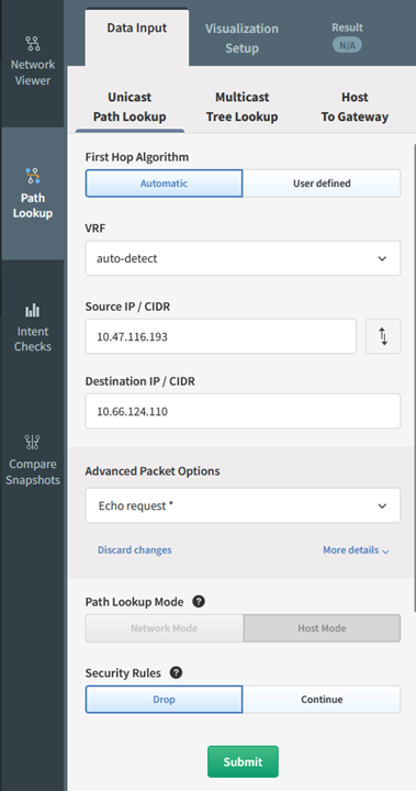
1.2.4 – By providing a source and destination within your network, IP Fabric can show the path that data takes through the network. These can be generated on-demand or configured to run automatically. The ability to generate these on-demand helps to satisfy requirement 1.2.4, as administrators can run these regularly to ensure they are kept current and accurate. This also provides an easy view of all devices that would be in-scope for a PCI compliance audit, meaning any devices within that data flow would need to be PCI compliant.
How does it work? When a snapshot of the network is taken, IP Fabric captures the state of each device, including CDP/LLDP, MAC table, and routing table information. That data is used to determine the relationship between devices. A graphical topology can be built from that relationship information.
In the above diagram, the traffic flow starts at the top left, from host 10.33.230.2 in site L33. The router L33R4 has equal-cost load balancing, splitting traffic across two paths. The traffic flows through an MPLS network to the L81 site. The presence of the transit cloud in the lower left indicates the flow traverses through a device (or multiple devices) that IP Fabric does not know (often this would be a service provider’s network). The traffic finally reaches the destination on L81R5.
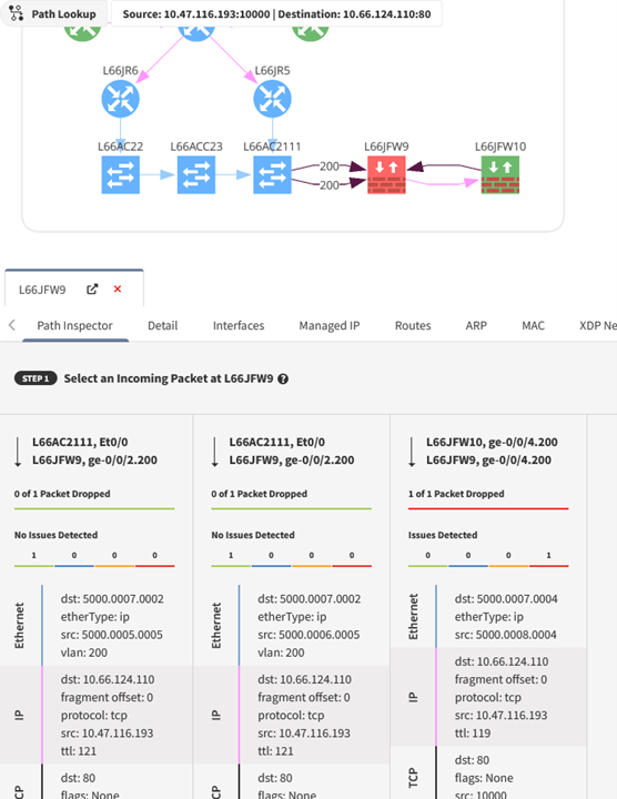
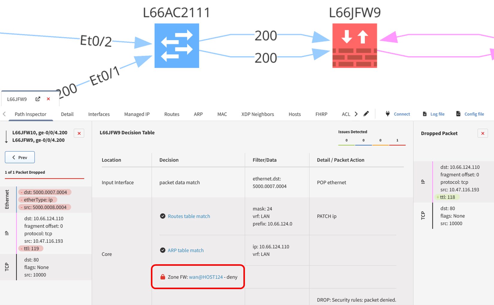
1.3.1 and 1.3.2 - Using the same path tracing tool allows you to determine whether traffic can enter or exit the CDE. A trace can be performed using specific source and destination IP addresses or using CIDR blocks and can include a defined protocol and port. This also allows for validation of the NSCs in place to ensure that only necessary traffic is flowing through these points. When a path trace is created, an intent rule is generated based on the intended status of that flow, be it pass or fail. Any deviation from what is expected or planned can be remedied by reinforcing the relevant NSCs to prevent any unnecessary traffic from entering, or exiting, where it should not be.
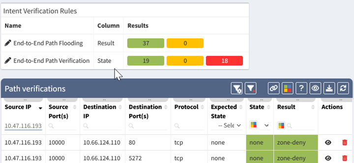
The above table shows the status of the path verification rules. The 5-tuple for each test is listed, along with the expected state (all allowed, or none allowed), the state of the test (all, part, or none of the traffic allowed), and the result which shows why traffic was blocked. The state is also color-coded, with green meaning the state matched expectations, and red signifying a deviation.
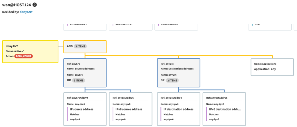
1.4.1 – Of particular interest within this requirement are 1.4.1.a and 1.4.1.b - These sub-requirements stipulate that configuration standards and network diagrams are verified (1.4.1.a), and in accordance with the documented standards for configuration standards and diagrams (1.4.1.b). With path tracing, you can determine where these NSCs are located, how they are configured, and whether this is sufficient to segregate trusted and untrusted networks. IP Fabric can also provide you with security assurance - You can standardize the management of your configurations and ensure that these align with your documented configuration standards required under 1.4.1.b. Standardizing the configuration management of NSCs reduces manual effort - Saving you additional time, effort, and brainpower in ensuring your NSCs are configured in accordance with your documented configuration standards before your next PCI compliance audit.
1.4.2 – Similarly to the requirements in 1.4.1, path tracing of the network and dataflow diagrams can be used to determine the flow of traffic between trusted and untrusted networks. As this requirement also stipulates that NSC configurations (and vendor documentation) be verified to determine if inbound traffic from untrusted to trusted networks is sufficiently restricted, IP Fabric’s security assurance can once again be used to standardize configuration management and ensure that these are sufficiently hardened against unwanted accesses.
1.4.4 – This requirement is also quite similar with regards to how IP Fabric can help. Using the network diagram that you have already built, you can verify if system components that store CHD are directly accessible from untrusted networks. Under 1.4.4.a, this means you have to verify your network and dataflow diagrams to ensure there is documentation that system components storing CHD is not directly accessible. Under 1.4.4.b, NSC configurations must be verified to ensure controls are in place to ensure CHD components are not accessible from untrusted networks. Again, with path tracing, and the ability to standardize configurations, you can ensure that these components are sufficiently protected and hardened against access from untrusted networks.
11.4.5 - As discussed in part 2, using your dataflow and network diagrams established by IP Fabric, you can verify whether you have sufficient segmentation in place. By locating the appropriate environments, you can verify whether segmentation is effective, prior to the investigation by an independent auditor.
Here's how simple IP Fabric makes this process:
This process can also leverage the API and webhook capabilities of IP Fabric. New path checks can be added programmatically and included in automation workflows. Webhooks can be configured to push information on failed intent checks into other platforms.
IP Fabric uses network configuration and state data to build out a representation of the network topology and can then determine how traffic would flow through the network, giving you all of the information that you need before your next PCI compliance audit. Adding intent rules to these path checks quickly and easily allows teams to identify problem areas. This visibility extends from a global topology view, down through a device level and into the detailed decisions made by network devices. That level of visibility simplifies both the environments' compliance state, as well as the process of gathering evidence to support either confirmation of compliance or the need for changes to achieve PCI compliance.
Follow us on LinkedIn and our blog, where we publish new content on a regular basis. For more information on how IP Fabric can help you to get to know your entire network inside and out, please request a demo here.
This article was co-authored by Dan Kelcher, Solutions Architect at IP Fabric